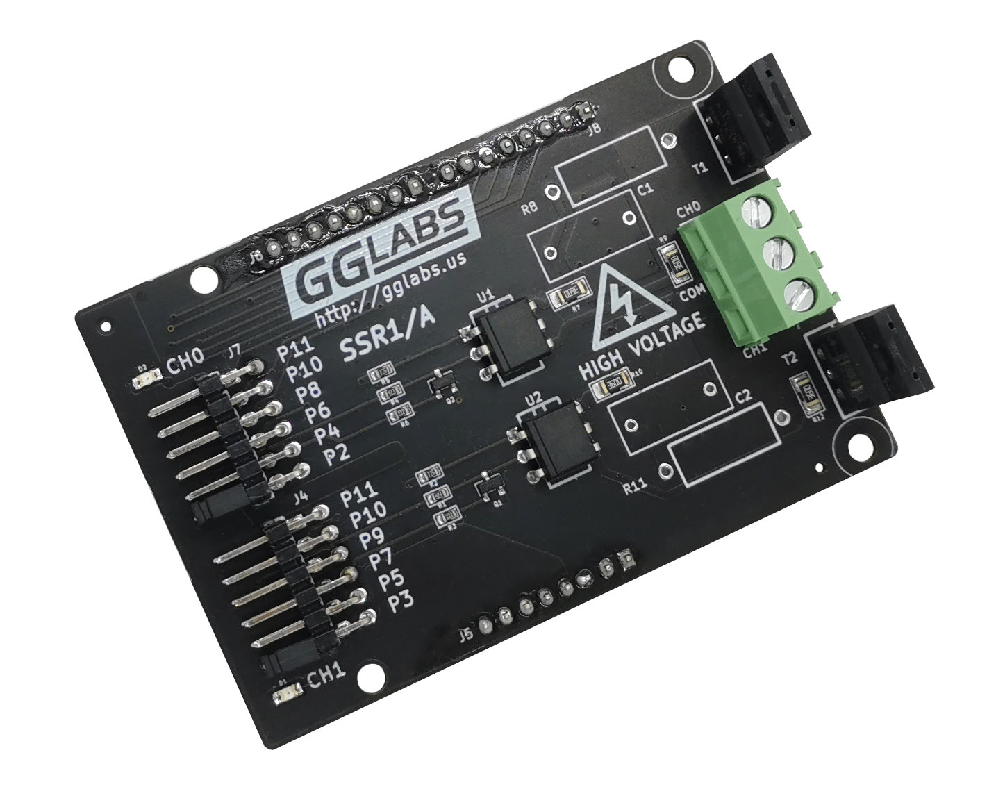
 Many MCU applications use electro-mechanical relays to control AC loads. While this is an excellent solution for occasionally turning on/off a load, it is not suited for frequent switching or PWM applications. SSR1/A is an opto-coupled solid state relay that can control two AC loads in a arduino shield form factor.
WARNING
 Parts of this circuit are not isolated from earth ground and contain potentially lethal voltages. Never touch any part of the circuit when powered on.
Use a safety isolation transformer during experimentation and troubleshooting.
Always use a fuse in series with the circuit to protect against short circuits.
Features
- each channel can be controlled by a choice of arduino pins
- opto-isolated for safety
- uses either zero-cross (MOC306x) or random phase (MOC305x) opto-triacs
- optional triac snubber
BOM notes
For zero-cross switching use MOC306x type opto-couplers, for random phase switching use MOC305x opto-couplers.
Controlling the Relay
The board has 2 channels that can be controlled independently. Channel 0 can be controlled with Arduino pin 2,4,6,8,10 or 11. Channel 1 can be controlled with Arduino pin 3,5,7,9,10 or 11. The jumpers on the board allow the user to select which pin controls the respective channel.
The SSR1/A expect digital signals so the pins used for controlling the channels need to be configured accordingly. Assuming the jumpers are inserted for pin2 and 3 add to setup():
pinMode(2, OUTPUT);

pinMode(3, OUTPUT);
Then setting the output HIGH will turn on the load and setting the output low will turn off the load.
digitalWrite(2, HIGH);  // Turns on channel 0

digitalWrite(2, LOW);   // Turns off channel 0
To check the code it's not necessary to connect the AC. Each channel has a LED that will light up when the channel is turned on even if there is not AC connected.