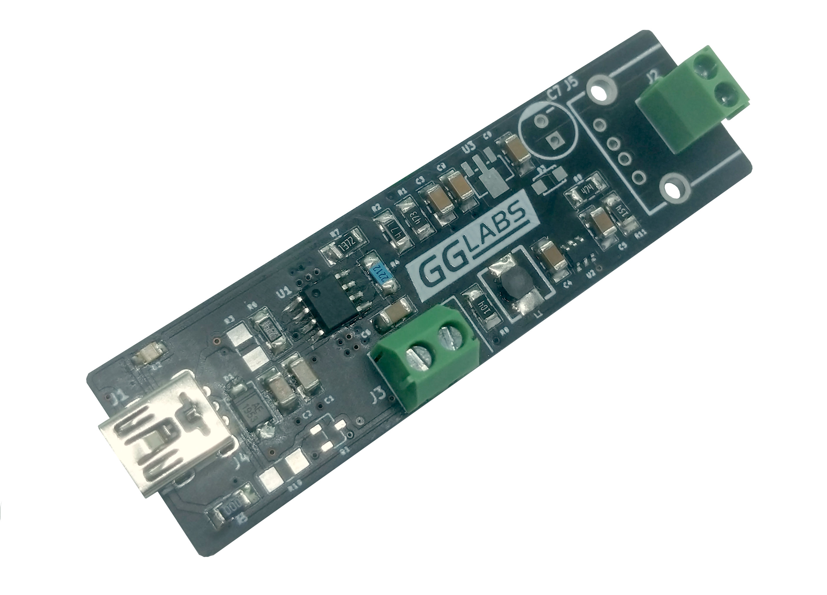
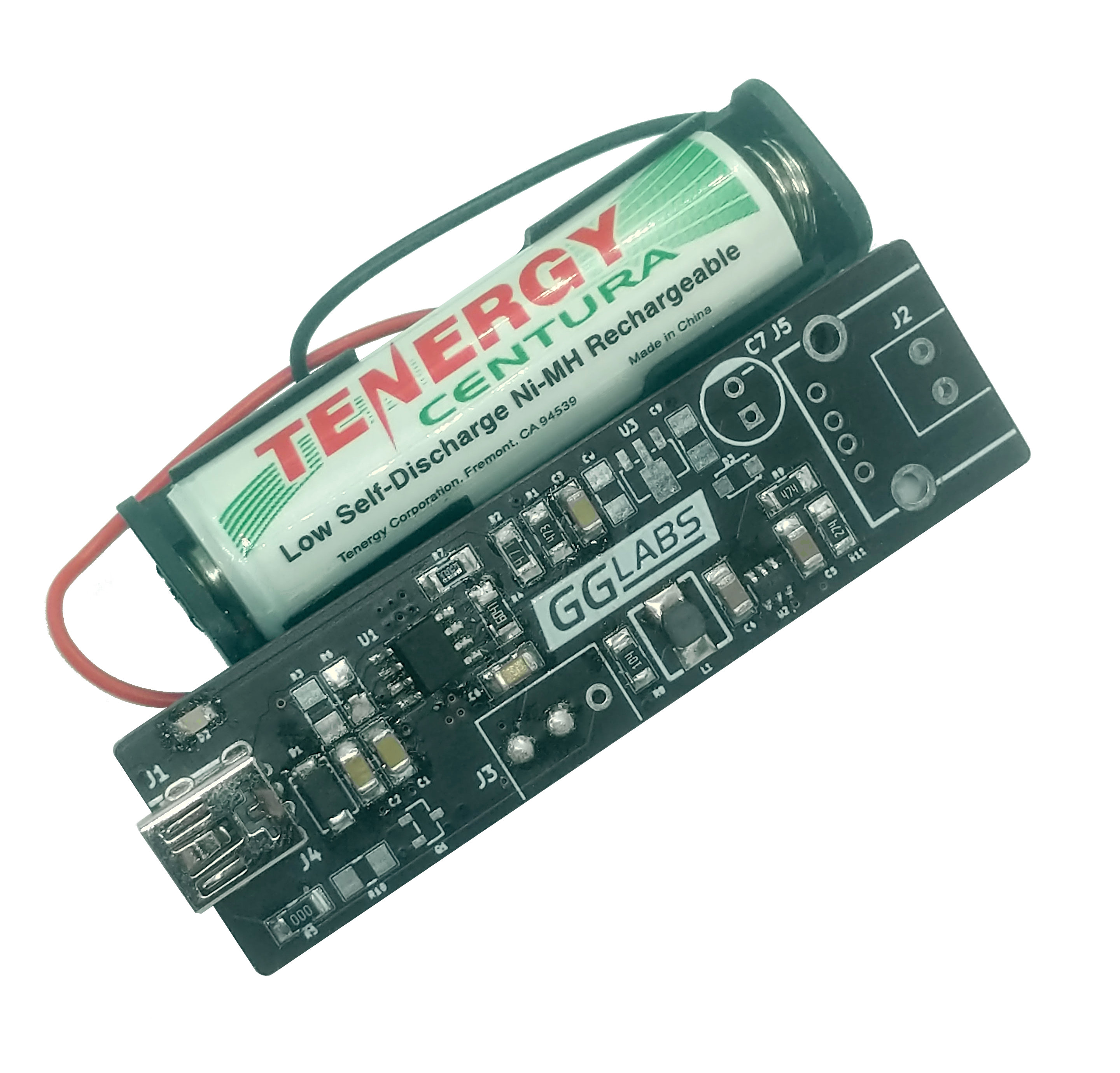
 Many MCU applications are portable and need a mean to provide power on the go. There are many solution based on Li-ION and Li-Polymer batteries. However Lithium chemistries need sophisticated charging and protection circuits to avoid dangerous situations. For lower power projects NiMH batteries provide a simpler and safer alternative. NUPS (NiMH UPS) can provide 3.3V and 5V using 1 to 3 AA or AAA NiMH cells.
Schematics
There are 3 main sections: battery charger, boost converter to provide the output voltage and an optional bypass regulator.
The battery charger is based on the Consonance CN3085. The integrated circuit contains all the blocks to implement a basic NiMH charging circuit: a constant current linear regulator, a charge termination circuit, a charge completion timer, a temperature sensor and a charge indicator. The CN3085 implements a simple voltage charge termination scheme, to avoid overcharging or undercharging, it is very important to set the termination voltage correctly. The value depends on the specific battery and the charging current. The battery datasheet or some battery characterization is required to select the optimal value.
The CN3085 charges the battery in 3 different steps: 10% of Iset during precharge (cell voltage below 70% of Vmax), 100% of Iset during constant current charge (cell voltage between 70% and 93.3% of Vmax), 60% of Iset during maintenance charge (above 93.3% of Vmax). Once in maintenance mode, charge is terminated by timer or by reaching Vmax.
R4 and R7 set Vmax, R6 sets Iset, R1 and C3 set the timer, R3 and R5 implement the temperature sensor. D1 protects the IC from voltage spikes when hot plugging.
The boost converter uses the Microchip MCP1640. This IC has a startup voltage of 0.65V which is more than sufficient even for a deeply discharged single NiMH cell. The IC has a 800mA typical maximum input switch current so the maximum output current heavily depends on the Vin/Vout ratio. The divider R9 and R11 determines the output voltage.
| # of cells | Vout | Iout |
|---|---|---|
| 1 | 3.3V | 100mA |
| 2 | 3.3V | 350mA |
| 2 | 5V | 150mA |
| 3 | 5V | 350mA |
 The optional bypass regulator U3 provides the output voltage while the adapter is plugged in. If the bypass regulator is not used the boost converter will steal some of the charger current. If the load is comparable to the charge current it will extend the charge time significantly.
