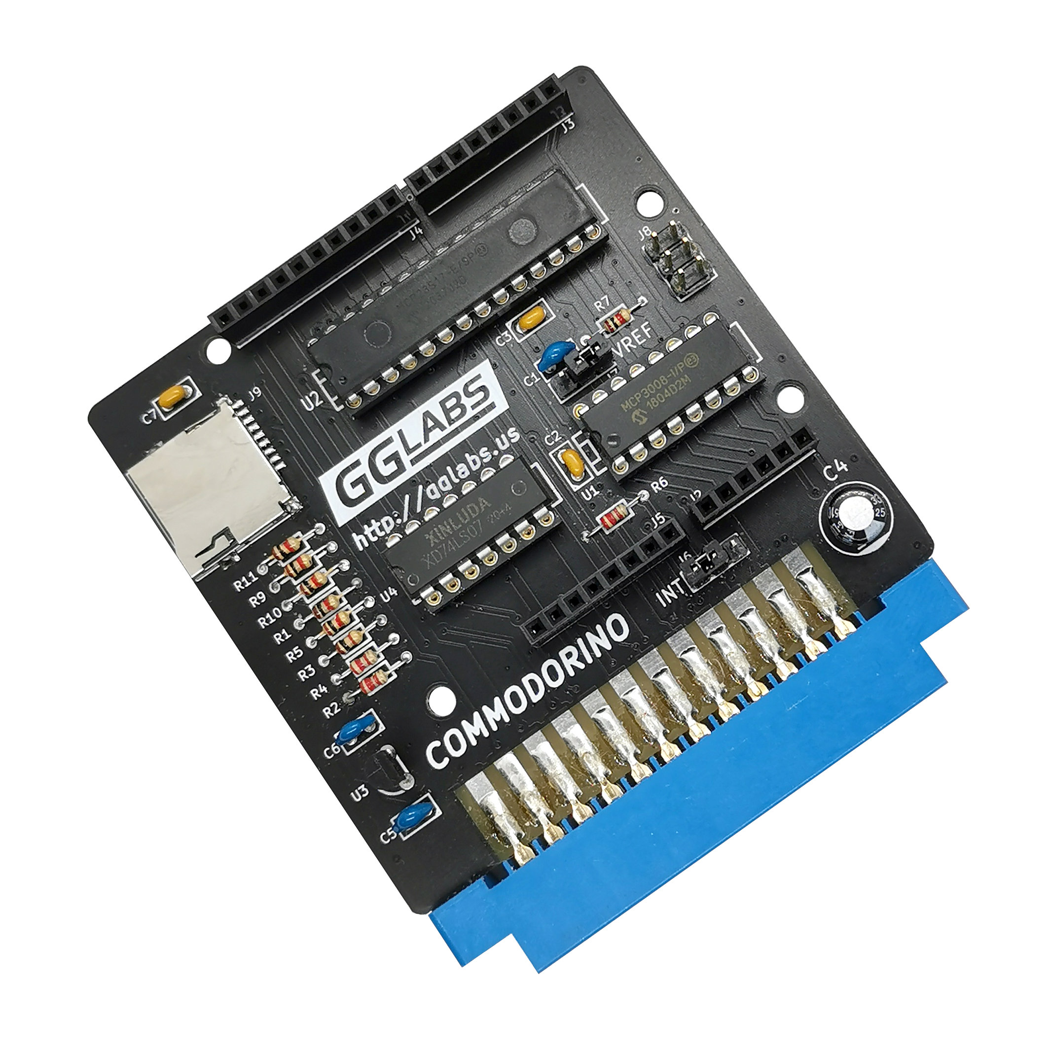
 Arduino shields are ubiquitous and provide a wide range of sensors and interfaces. Commodorino allows their use on a Commodore 64. The interface provides good compatibility with the Arduino Uno platform. Digital I/O, Analog In, SPI, I2C and limited interrupt and Serial port are implemented and additional Micro SD card socket is available for future expansion. A C library is provided to aid porting Arduino code and a FORTH dictionary to aid interactive development.
Features
Our staff tried to implement as much functionality as possible within the limitation of the Commodore platform.
Most features are close enough that sketches can be ported without too much trouble. The most notable limitation is the poor performance of the serial port and its interference with the interrupt system.
| Feature | HW Support | SW status | Notes |
|---|---|---|---|
| Digital I/O | Fully implemented | Fully implemented | input Pull-Ups are not available on all pins |
| Analog I/O | Fully implemented | WIP | |
| External Interrupt | Most pins are interrupt capable | WIP | only D0 is a fast interrupt |
| SPI | Master Only | Fully Implemented | max speed ~ 170KHz |
| I2C | Master Only | WIP | |
| Serial | Up to 2400 baud | WIP | interferes with interrupt capability |
| SD Card | Fully implemented | WIP | Dedicated Chip Select |
| Aref | Jumper | N/A | SW switching is not possible |
Schematics
Most of the GPIO functionality is implemented using the Microchip MCP23S17 GPIO expander, the analog input functionality is implemented using the Microchip MCP3008 A/D converter. Both devices are controlled using a SPI interface. The CIA hardware shift register is used to implement a high performance SPI master interface. CIA1 is used to generate the serial clock and transmit data. CIA2 is used for receive data.
The SPI interface is also used for the micro SD card. Level shifting is implemented by the open collector buffer U4. I2C is implemented by bit banging CIA1 PB6 and PB7.
Jumper J6 selects the interrupt source between the GPIO expander and the D0 pin (required for serial support).
Jumper J7 selects the ADC Vref between 5V and external reference voltage. The regulator U3 provides 3.3V for the micro SD card and the shield connector.
Software
We implemented two interfaces to facilitate the use of Arduino shields. One interface in C that resembles the Arduino API to facilitate porting of existing sketches/libraries. For interactive development we also created a FORTH dictionary. Programming in BASIC is also possible using PEEK and POKE but it is quite cumbersome. A BASIC extension could be implemented to make development more pleasant.
C API
The C API is written using the cc65 compile suite. The include "commodorino.h" describes the available functions. Currently all the files should be linked to the Commodorino "sketch" to obtain an executable prg file.
void    __fastcall__ setup(void);

void    __fastcall__ loop(void);
The library includes a main function that calls the standard Arduino setup and loop. These behave exactly the same as Arduino. setup() is called once during program startup and loop() is called forever.
void    __fastcall__ pinMode(uint8_t pin, enum pin_mode_t mode);

void    __fastcall__ digitalWrite(uint8_t pin, uint8_t value);

uint8_t __fastcall__ digitalRead(uint8_t pin);
The digital pin interface follows closely the Arduino API. A few pins (D0, D1, A4 and A5) are directly connected to CIA1 pins and do not support INPUT_PULLUP, however these can toggle significantly faster as there is no need for a relatively slow SPI transaction. GPIO expander register state is cached on the C64 to speed up read-modify-write transactions.
uint8_t __fastcall__ SPI_transfer(uint8_t val);
The function works the same as the Arduino SPI.Transfer(). Setting the SPI speed is currently not implemented.
FORTH dictionary
We also wanted to provide an interactive environmet to interact with the shields. We decided that FORTH provided the right mix of performance and interactivity. We choose DurexFORTH as our target environment because it is under active development and works well with SD2IEC.
INIT ( -- )
The INIT word must be used at the beginning of the program to initialize the SPI and set all pins to a known state.
DIGWR ( VAL PIN -- )

DIGRD ( PIN -- VAL )

PINMODE ( VAL PIN -- )
Words to control the state of digital pins. Currently can only address pin 0 to 11.
 SPWR ( VAL -- )

SPRD ( -- VAL )
Write or read one byte using SPI
