A new version of this project is available here
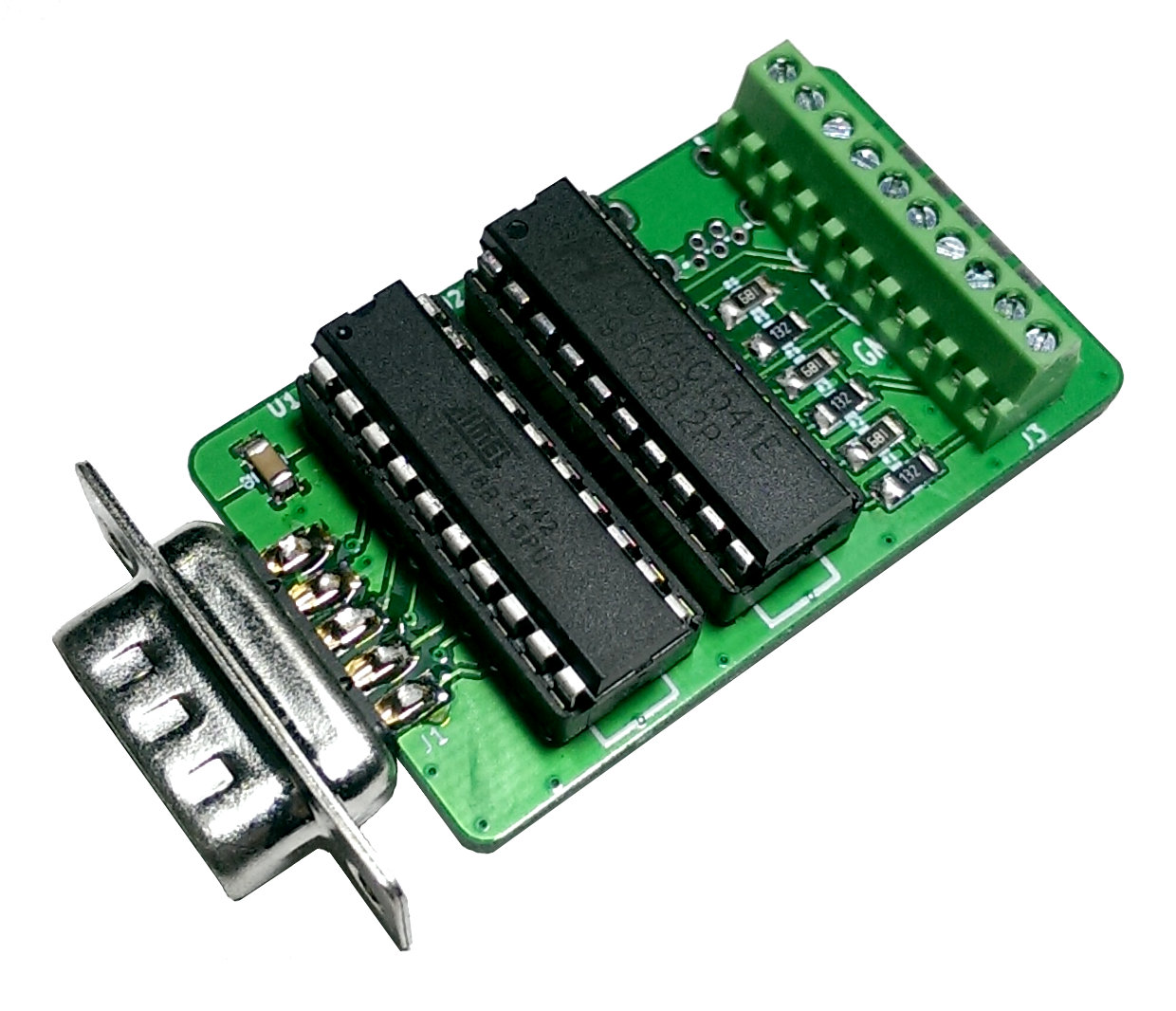
 The 80 column output of the Commodore 128 is the same digital RGBI used by the original IBM CGA graphics adapter. Unfortunately nowadays is quite difficult to find a monitor with the suitable RGBI input. The CGA2RGB adapter will convert the TTL RGBI to analog RGB suitable to be connected directly to a 15KHz capable RGB monitor or to the popular Gonbes GBS-8200 VGA converter.
The basic circuit is a triple 2-bit digital to analog converter. U1 decodes the 4-bit RGBI input to the full 2-bit per color component and generates the composite sync needed for the GBS-8200.
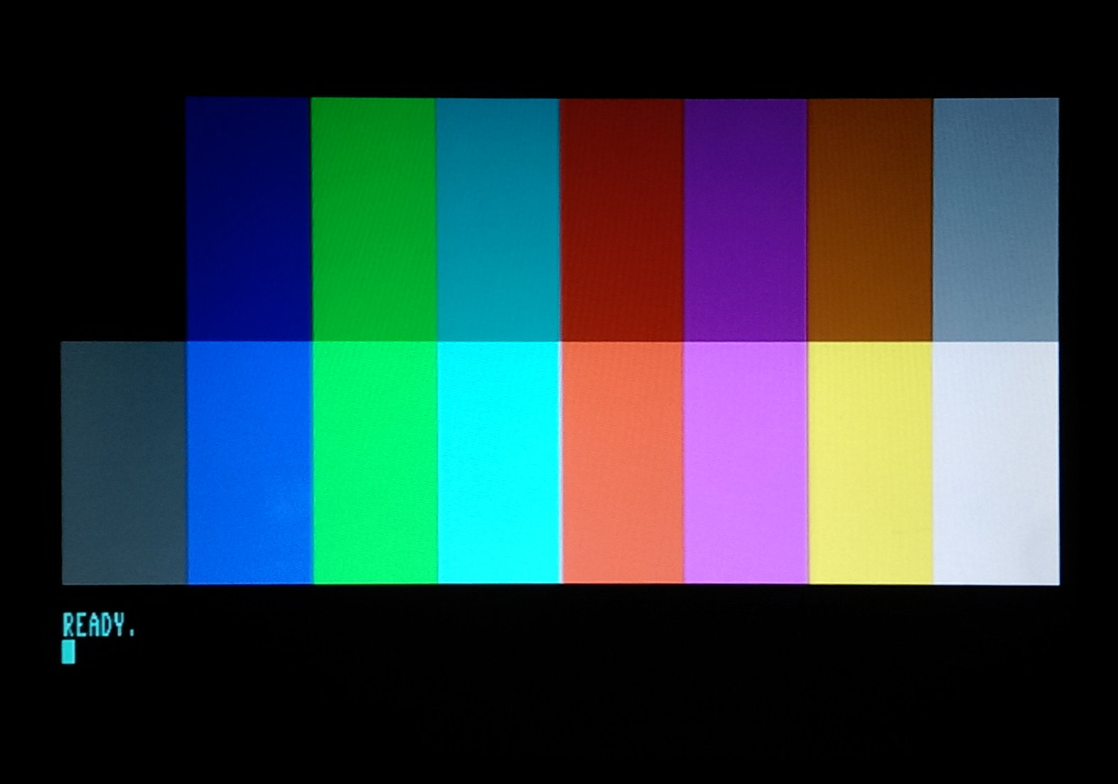
The decoding follows the standard CGA color table which includes a special case for color 6.
| Commodore Color Number | CGA Color Number | RGBI | Color | R | G | B |
|---|---|---|---|---|---|---|
| 1 | 0 | 0000 | Black | 00 | 00 | 00 |
| 7 | 1 | 0010 | Blue | 00 | 00 | 10 |
| 6 | 2 | 0100 | Green | 00 | 10 | 00 |
| 12 | 3 | 0110 | Cyan | 00 | 10 | 10 |
| 3 | 4 | 1000 | Red | 10 | 00 | 00 |
| 9 | 5 | 1010 | Magenta | 10 | 00 | 10 |
| 10 | 6 | 1100 | Brown | 10 | 01 | 00 |
| 16 | 7 | 1110 | Light Grey | 10 | 10 | 10 |
| 13 | 8 | 0001 | Grey | 01 | 01 | 01 |
| 15 | 9 | 0011 | Light Blue | 01 | 01 | 11 |
| 14 | 10 | 0101 | Light Green | 01 | 11 | 01 |
| 4 | 11 | 0111 | Light Cyan | 01 | 11 | 11 |
| 11 | 12 | 1001 | Light Red | 11 | 01 | 01 |
| 5 | 13 | 1011 | Light Magenta | 11 | 01 | 11 |
| 8 | 14 | 1101 | Yellow | 11 | 11 | 01 |
| 2 | 15 | 1111 | White | 11 | 11 | 11 |
U2 buffers the decoded signals and generates the analog signal through a resistor network.
The board requires a 5V power supply. It can be powered directly from the GBS-8200 or using the J4 mini USB port.
Performance Notes
The image quality of the GCA2RGB, like all analog video connections, heavily depends on the cable used. A high quality 75ohm coaxial cable is recommended for the video signals. The standard multi colored cable included in the GBS-8200 is not an optimal choice.
The following images show the difference between the standard cable and a good quality coaxial cable. In the first image is easy to note the large signal reflection due to impedance mismatch. The issue is compounded with additional discontinuities due to sub optimal grounding on the GBS-8200 PCB. The second picture shows a significant improvement.
For best quality we recommend to keep the wiring between the CGA2RGB and the GBS-8200 as short as possible.


