A new version of this project is available here
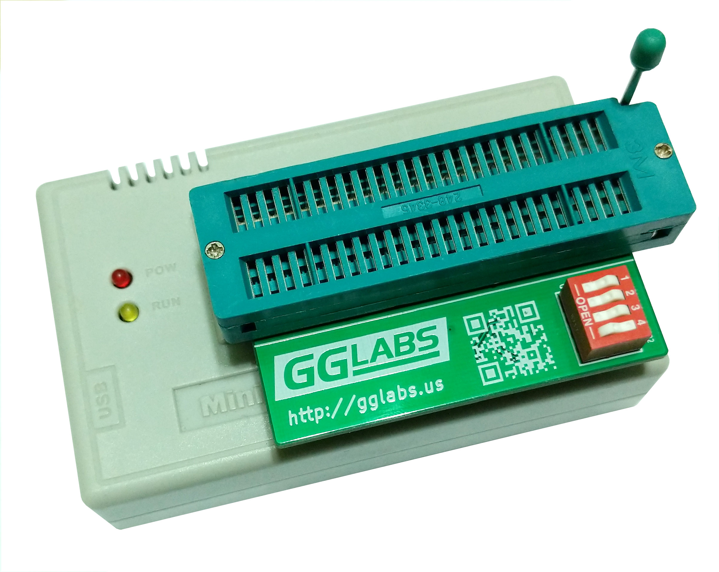 The Minipro TL866 is very popular among hobbyist because of its low price and ease of use. Its list of supported chips is however somewhat limited compared to more expensive professional programmers. The E2R16v2 adapter adds support for the ROM pinout compatible EPROM of the 27C400/800/160 and C322 series.
The design is based on the original E2R16 V2. It remaps the 27C4096 pins to the corresponding 27Cxxx pins. A 4-bit dip switch is used to select the 512KB bank to program for the larger chips.
A18 and A19 are trivial, they default to low and setting the corresponding switch to ON will set the address line high.
The circuit on A20 is necessary because pin 32 is assigned to VPP on the C800/C160 and to A20 on the C322. On the C322 the programming voltage should be applied to pin 13 (OE#). Dip switch 4 selects the C322 mode and re-routes VPP to the correct pin. D1 and R7 allows OE# from the programmer to work as expected while blocking the VPP voltage from flowing back into the programmer. Q4 and R12 prevent VPP from interfering with OE# during C322 reads and address the compatibility with some TL866. R11 is necessary to ignore A20 on while not in C322 mode.
The new layout also addresses the mechanical interference with the ZIF socket.
EPROM Programming
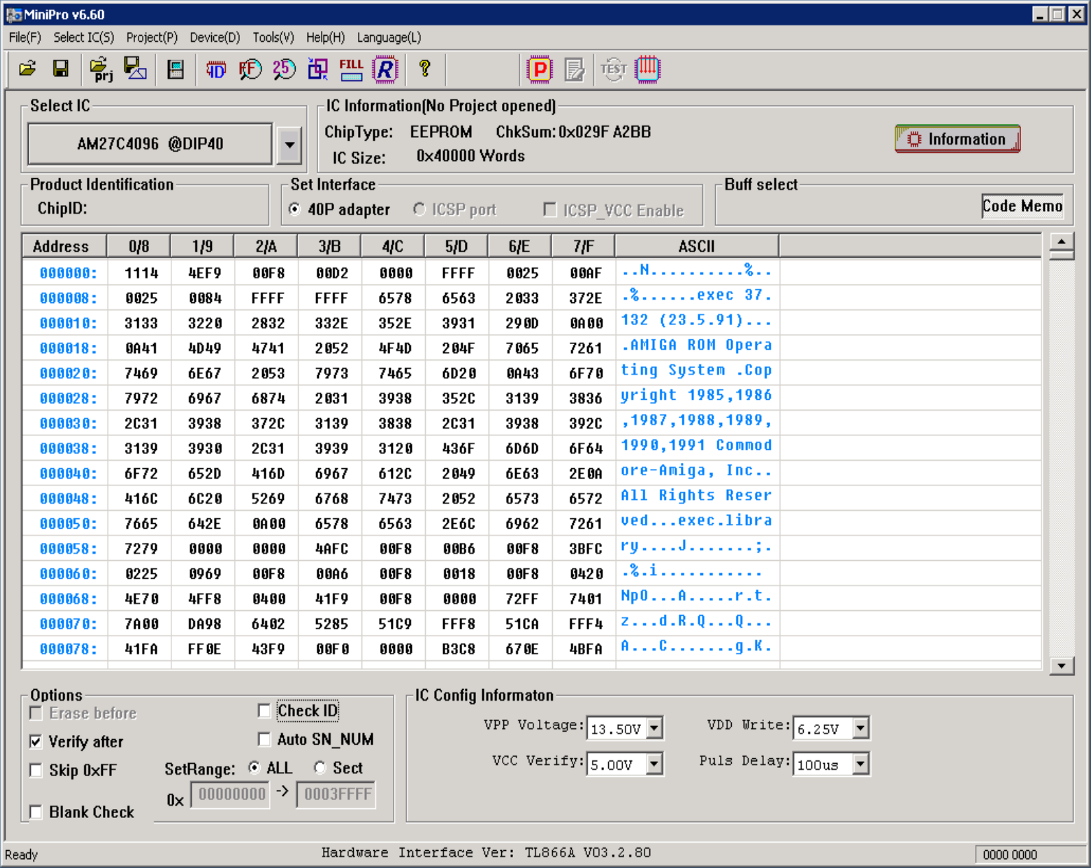
To use the adapter to read or write 27Cxxx EPROMs select 27c4096 and de-select "check ID" in the Minipro GUI. Set the DIP siwtch according to the 512KB bank that need to be read/written. Additionally, for programming make sure the section "IC Config Information" is set according to the datasheet of the specific EPROM being programmed.
Then read and write as usual. Repeat for every 512KB bank.
BOM
| Qty | Ref Des | Package | Value |
|---|---|---|---|
| 1 | U1 | DIL | 42 or 48 pin socket |
| 2 | U2 | SIL | 20 pin 100mil (2.54mm) pitch male headers |
| 3 | Q1,Q2,Q4 | SOT-23 | MMBT3906 PNP transistors |
| 1 | Q3 | SOT-23 | BSS138 N-channel mosfets |
| 1 | D1 | SOD123 | 1N4148 diode |
| 2 | C1,C2 | 1206 | 0.1uF 16V X7R capacitors |
| 9 | R3,R4,R5,R6,R8,R9,R10,R11,R12 | 1206 | 10k ohm resistors |
| 1 | R7 | 1206 | 2.2k ohm resistor |
| 1 | P1 | DIL | 4-position DIP switch |
| Attachment | Size |
|---|---|
| M27C400 Datasheet from ST Microelectronics | 123.3 KB |
BOM
Is there a BOM for the board? I'm now sure what the device types for PNPs, FET and Diode are?
BOM Table Added
Just added a BOM table to the page
Compatibility
Hi! Will this also work on TL866II Plus, or is it TL866 only?
It should work on the TL866II as well
I did not test it personally but users have reported it does work on the TL866II as well.
Unable to program 27c400s with my TL866II Plus
I have checked my build over and over and cannot seem to get it working to program 27c400's with my TL866II Plus. It always writes zeros to all addresses ending in $40-$4f and $c0-$cf. I bought 2 different batches of 27c400's just to make sure it wasn't a problem with the chips. I have tested about 10 different chips with the same results. I was able to actually program 1 when I first got it, but not since. I'm sure there is an issue with my board, and maybe it's obvious but I can't figure it out. Any idea as to what connections to look at that might cause this problem?
Check all connenctions
If you can burn any pattern it means the active circuitry is probably correct.
I would try to check with an ohmmeter that all address pins are connected properly between the header and the socket.
E2R16v2.1 not working properly
Something strange happens with the E2R16v2.1 PCB i bought en build. I build
it with the c322 setup and it is not working with the c400 and c800. So i
removed the c322 parts and build the easy setup and it works. I think that
there is something wrong with the c322 setup, all parts i used are new and
tested. Maybe it is the TL866 II Plus version why it is not working? Please
help.
Regards
TL866 II Plus
Some TL866 II+ cannot detect correctly the adapter.
To fix the issue a 2.2k resistor should be added between pin 20 of the programmer socket (U2) and VCC.
These changes are reflected in the V2.2 of the adapter.
ST M27V160 10XF1 settings
After frying one of these chips I’ve got a good set of settings that’s good for multiple program/erase cycles. They are: chip AM27C4096 VPP 12.5v, VDD 5.0v, VCC 3.3v pulse delay 50us. That’s all for now.
EPROM settings
Different chips will require different settings. The specific chip datasheet has the required information.