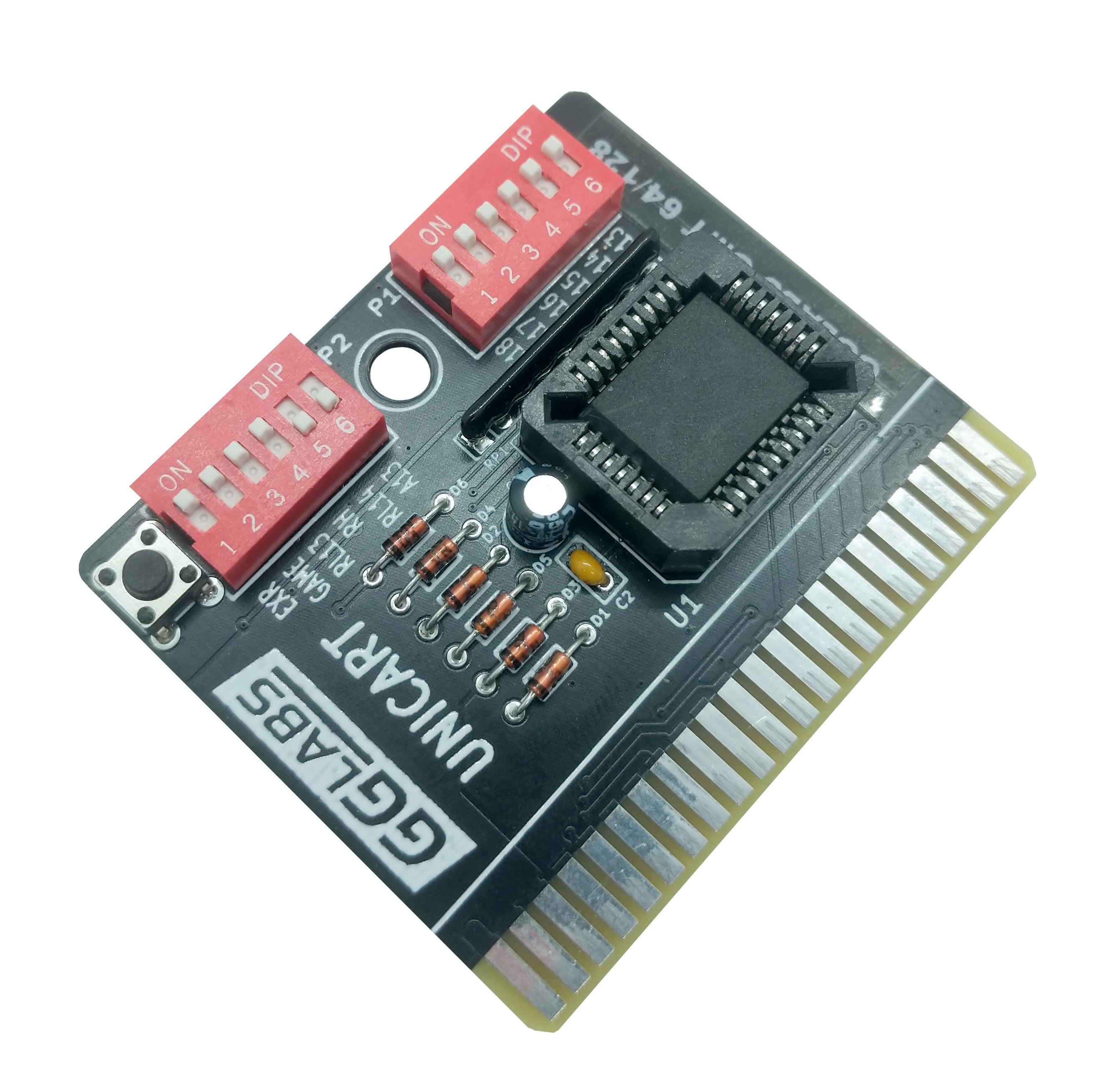
 After we developed the UNICART/D many customers asked for a more compact version of the cartridge without the pass-through connector. The board uses one standard PLCC32 flash ROM up to 4Mbit. In C64 mode 8K, 16K and 16K Ultimax cartridge modes are supported. In C128 mode both 16K and 32K cartridges are supported.
The schematics is heavily based on the UNICART/D. The flash ROM is directly connected to the CPU bus. The most significant bits of the address are connected to dip switch P1 which selects the bank within the flash ROM.
Dip switch P2 selects the cartridge mode and size. Refer to the tables below for dip switch configuration. For C64 only configurations a 4 position dip switch can be used on P2-1 to P1-4. For C128 only configurations a 3 position dip switch on P2-4 to P2-6 is sufficient.
Diodes D1 and D3 form a wired AND to generate the ROM chip enable. D2, D4 and D5 are not strictly necessary but they protect the system bus in case of incorrect dip switch configuration. D6 is to be able to write the flash ROM in system. This feature is unfortunately not tested as we didn't have the time to write the software.
Resistors R1-R6 are used to replace P2 in fixed configurations.
| DIP | Name | C64 8K | C64 16K | C64 Ultimax | C128 16K | C128 32K | Notes |
|---|---|---|---|---|---|---|---|
| P2-1 | EXROM | ON | ON | OFF | OFF | OFF | Not used for C128 |
| P2-2 | GAME | OFF | ON | ON | OFF | OFF | Not used for C128 |
| P2-3 | ROML13 | OFF | ON | ON | OFF | OFF | Not Used for C128 |
| P2-4 | ROMH | OFF | ON | ON | OFF | ON | |
| P2-5 | ROML14 | OFF | OFF | OFF | OFF | ON | Not used for C64 |
| P2-6 | A13 | OFF | OFF | OFF | ON | ON | Not used for C64 |
| P1-6 | EA13 | RA13 | OFF | OFF | OFF | OFF | |
| P1-5 | EA14 | RA14 | RA14 | RA14 | RA14 | OFF | |
| P1-4 | EA15 | RA15 | RA15 | RA15 | RA15 | RA15 | Only used on 512Kbit (64KB) or larger ROMs |
| P1-3 | EA16 | RA16 | RA16 | RA16 | RA16 | RA16 | Only used on 1Mbit (128KB) or larger ROMs |
| P1-2 | EA17 | RA17 | RA17 | RA17 | RA17 | RA17 | Only used on 2Mbit (256KB) or larger ROMs |
| P1-1 | EA18 | RA18 | RA18 | RA18 | RA18 | RA18 | Only used on 4Mbit (512KB) ROMs |
Please note that the polarity of P1 is reversed (i.e. ON means 0 and OFF means 1).
| P1-6 | P1-5 | P1-4 | P1-3 | P1-2 | P1-1 | 8K addr | 16K addr | 32K addr |
|---|---|---|---|---|---|---|---|---|
| ON | ON | ON | ON | ON | ON | 0x00000 | - | - |
| ON | ON | ON | ON | ON | OFF | 0x02000 | 0x00000 | - |
| ON | ON | ON | ON | OFF | ON | 0x04000 | - | - |
| ON | ON | ON | ON | OFF | OFF | 0x06000 | 0x04000 | 0x00000 |
| ON | ON | ON | OFF | ON | ON | 0x08000 | - | - |
| ON | ON | ON | OFF | ON | OFF | 0x0A000 | 0x08000 | - |
| ON | ON | ON | OFF | OFF | ON | 0x0C000 | - | - |
| ON | ON | ON | OFF | OFF | OFF | 0x0E000 | 0x0C000 | 0x08000 |
| ... | ||||||||
| ON | OFF | OFF | OFF | ON | ON | 0x38000 | - | - |
| ON | OFF | OFF | OFF | ON | OFF | 0x3A000 | 0x38000 | - |
| ON | OFF | OFF | OFF | OFF | ON | 0x3C000 | - | - |
| ON | OFF | OFF | OFF | OFF | OFF | 0x3E000 | 0x3C000 | 0x38000 |
Creating a ROM image
The ROM can contain a mix of both C64 and C128 cartridge images of any size. The only limitation is that each ROM image must be aligned at boundaries equal to its size. I.e. 8K images can be placed at any address multiple of 8K, 16K images can be only placed at addresses multiple of 16K and so on. With this scheme the absolute maximum for wasted space is 24K (one 16K and one 8K slot). In many cases the wasted space can be reduced to zero.
The ROM images must be in bin format. To convert crt files the utility cartconv from the VICE emulator can be used.
cartconv -i image.crt -o image.bin
to combine the images in linux:
cat image_1.bin image_2.bin image_n.bin > combined.bin
or in windows:
type image_1.bin image_2.bin image_n.bin > combined.bin
Credits
This cartridge combines all the wiring diagrams for the C64 and C128 cartridges from world of Jani into a single universal design. See the links below.
