A new version of this project is available here
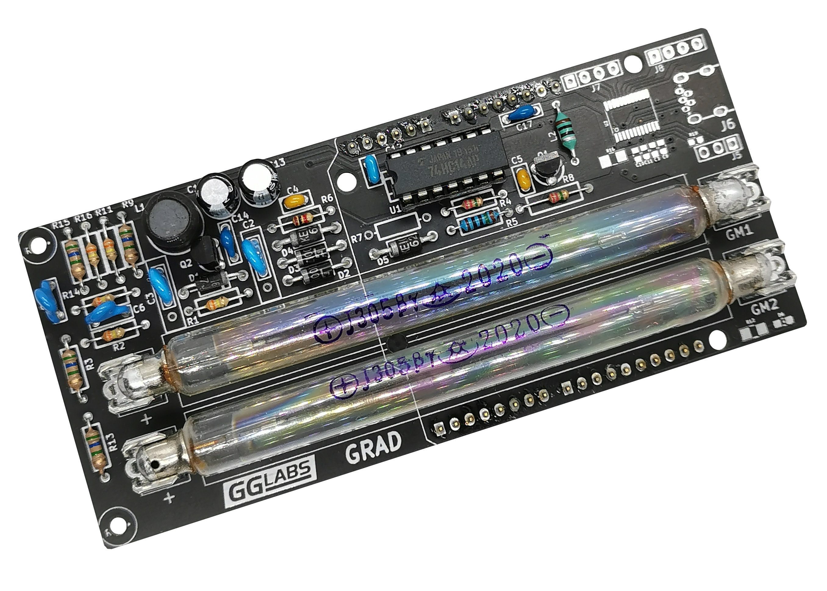
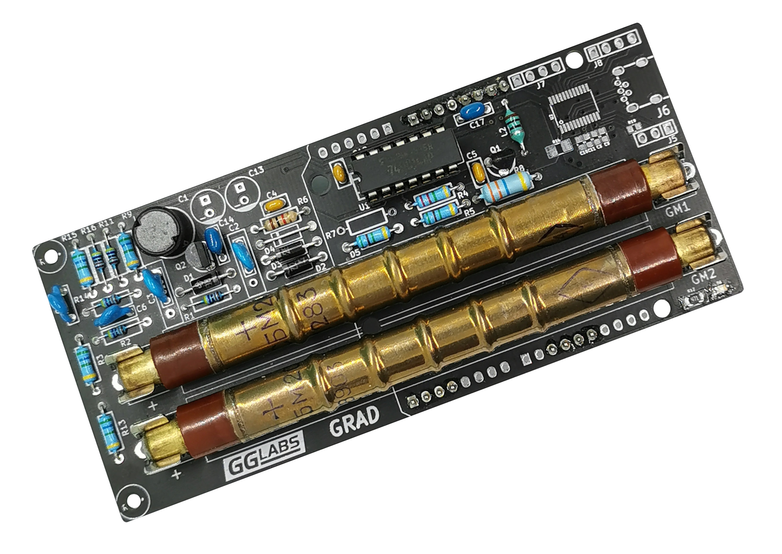 Like many other hobbyist we have always been fascinated by radioactivity and the sensors to detect it. Geiger-Müller tubes are a common and relatively inexpensive way to measure radiation. GRAD is a complete solution for radiation counting in an Arduino shield form factor. Its main features are dual tube support to increase sensitivity and very low power consumption.
Introduction to Geiger-Müller Counters
Every Geiger-Müller counter requires 4 essential functional blocks.
Geiger-Müller Tube
The tube has two terminals and is filled with a low pressure gas mixture. When biased with the appropriate voltage the gas will ionize and briefly conduct electricity every time it is hit by radiation. Depending on the tube type it is possible to detect alpha, beta and gamma particles. The SBM-20 used in the GRAD is sensitive to gamma and high energy beta.
High Voltage Power Supply
The tube must be operated in the Geiger Plateau. This is a region where the pulse count is almost independent of the bias voltage. For common tubes the bias voltage is between 400 and 500V. The SBM-20 optimal point is around 400V.
Pulse Detector
The pulses out of the tube are very short and variable voltage. The pulse detector conditions the signal so it can be easily counted by the following stage.
Pulse counting
Pulses are counted over a fixed amount of time to calculate a CPS (counts per second) or CPM (counts per minute) value. This can be roughly converted to a dose rate by using the parameter on the tube datasheet.
Arduino is used for pulse counting and its visualization and/or logging.
Schematics
There are many circuits on the web for Geiger-Müller tube power supplies. Many are boost converters built around the 555 timer, some open loop, some with feedback. The open loop designs were not considered as they require tuning per board and do not provide a stable voltage at high pulse counts.
Closed loop design are more suitable as they provide the required stability. However, to keep overall power consumption low, special attention should be paid to the feedback loop (12uA of current @ 400V is ~5mW).
To avoid the power penalty of high voltage feedback, the most elegant solutions use a non isolated step-up transformer and detect the voltage on the primary side like the Analog Devices LT3420.
We implemented a simple switch mode boost converter with a very low current feedback. Our design is heavily based on the Theremino Geiger adapter. We mixed the SMD, DYI and "Flintstones" deigns in a fully PTH design with zener diode feedback.
The Schmitt trigger inverter U1F, R4 and C5 form a oscillator that generates the pulses to drive the main switch Q2. U1A, U1B and U1C are in parallel to increase Q2 base current.
The feedback is implemented with a series of very low leakage current zener diodes. When the output voltage exceeds the zener voltage Q1 turns on and stops the oscillator. When the output voltage drops again Q1 will turn off releasing the oscillator. R1 and C3 further reduce the output ripple. Additional series resistors feed each tube separately (R2 and R3 for GM1, R13 and R14 for GM2).
Pulses are picked up from the high voltage side of the tube using a DC blocking capacitor (C6 and C7). The pulse is shaped by the remaining Schmitt trigger inverters.
J1-J4 are the standard Arduino connectors. GRAD only uses D2 and D3 (this is the only software visible difference from the previous GRAD-A00) and 5V power.
D2 and D3 were chosen as they are interrupt pins on the Arduino UNO. This allow the arduino to count pulses in the background while it is performing other actions.
For standalone operation a footprint for a Silicon Labs EFM8UB1 USB MCU is also provided.
Performance
The power supply consumes 325uW (65uA) at 5V, In battery operated devices the board can also be powered with 3.3V. At the lower voltage the power drops to 150uW (45uA).
Arduino Sample Code
A simple arduino sketch to drive the counter is available in the files section below.
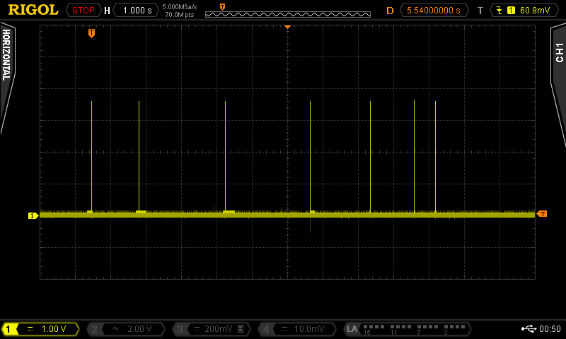
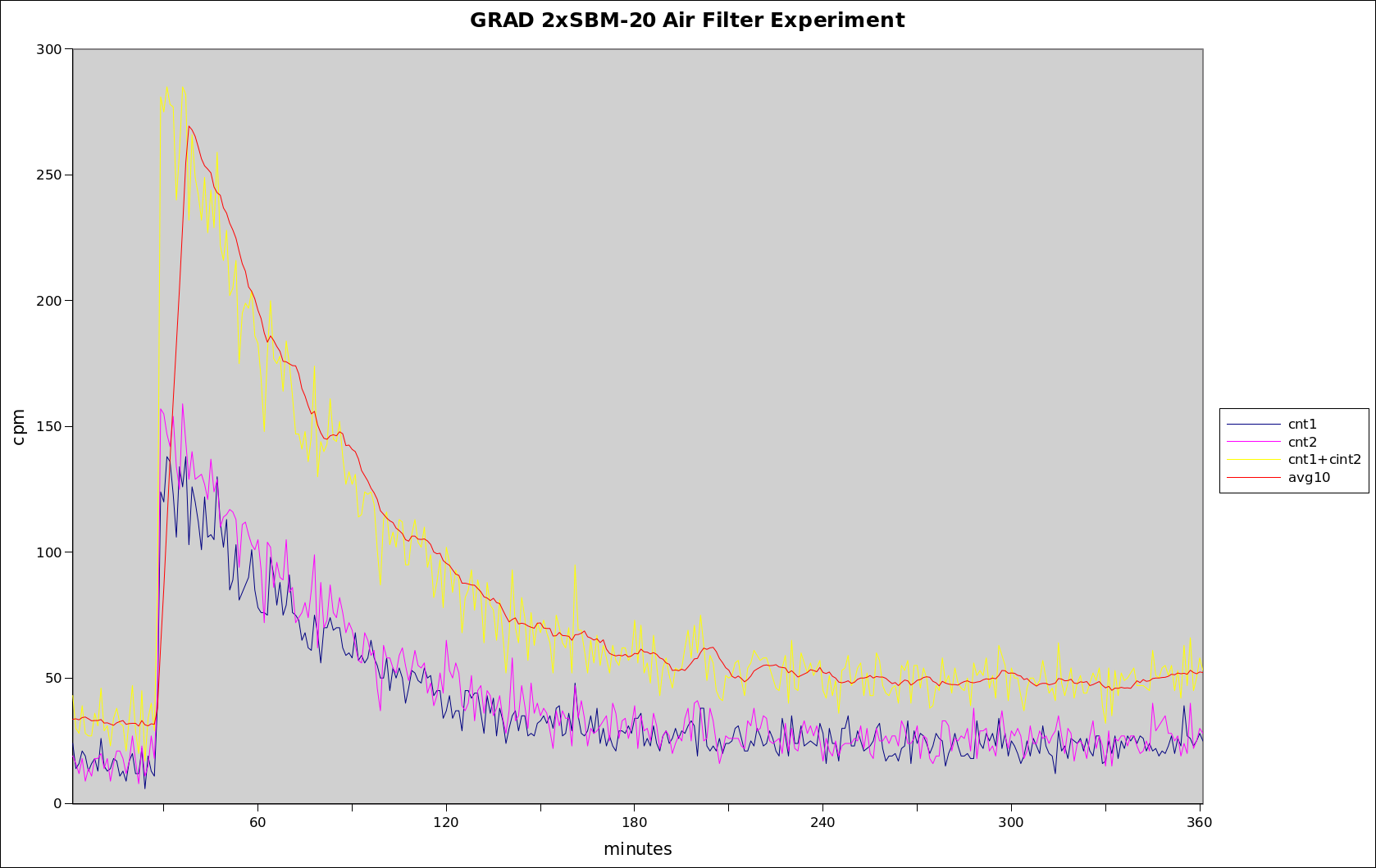
Every 60 seconds, the software will output a csv row with a sequential number, raw count for each tube, a moving average of counts and a uS/h dose rate. The chart below shows the background radiation in Santa Clara, CA measured using GRAD with two SBM-20 tubes.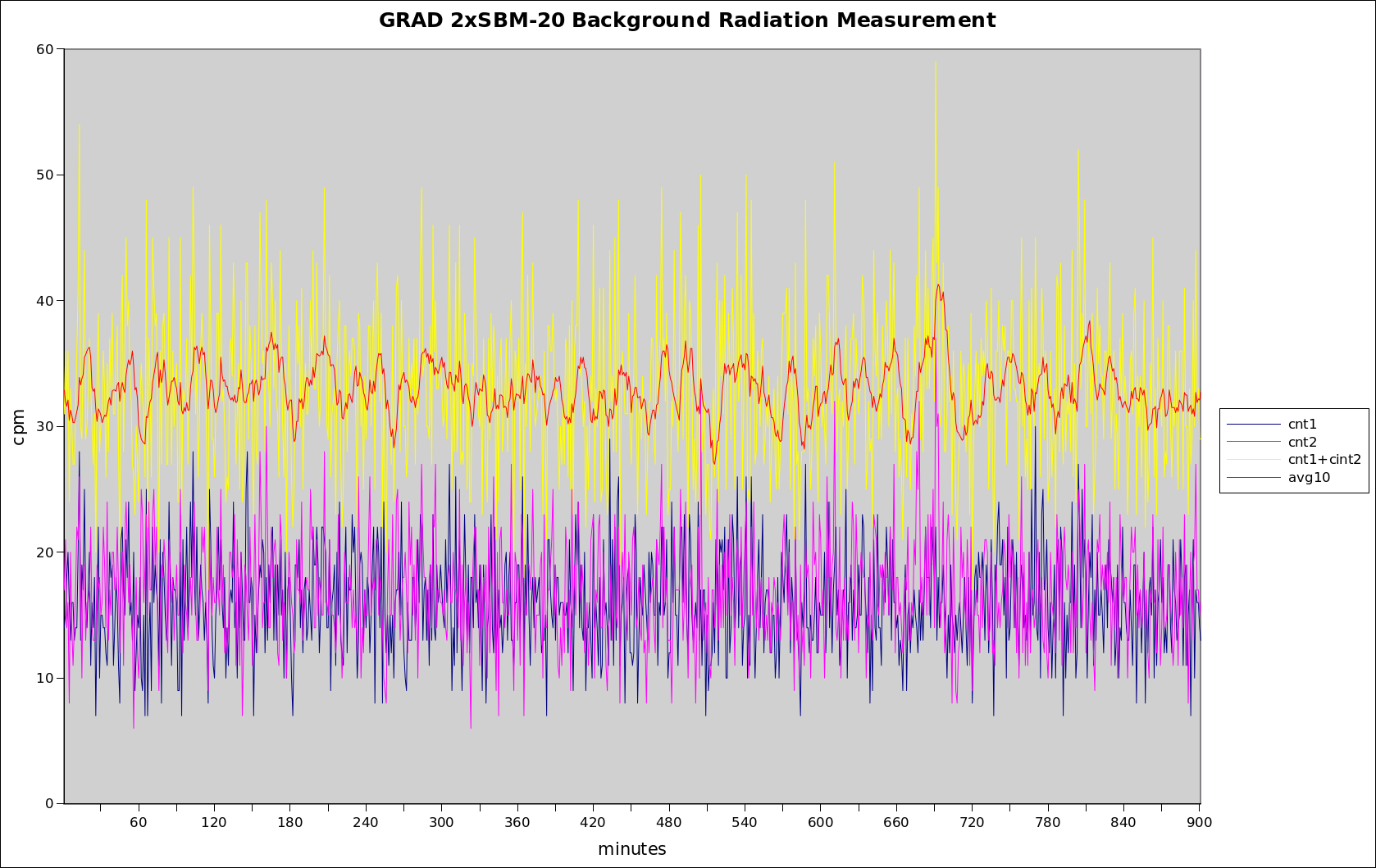
Seq , cnt1 , cnt2 , avg10 , uS/h

1 , 14 , 19 , 33.0 , 0.075

2 , 9 , 17 , 32.3 , 0.073

3 , 16 , 12 , 31.8 , 0.072

4 , 16 , 24 , 32.5 , 0.074

5 , 13 , 11 , 31.6 , 0.072
There are a few defines at the beginning that are configurable to match the HW configuration and/or user preferences. The first set configures the Geiger-Müller tube parameters and the moving window size for the reporting.
#define CPM2USV 220 // tube CPM to uS/h conversion factor The CPM2USV parameter is the count per minute for 1uS/h for your particular tube. Unfortunately there is no published "correct" number for this parameter. For the SBM-20 radiation enthusiasts on the web use values that range from 130 to 220 (conversion factor of 0.0075 to 0.0045).
#define TUBES 2 // number of tubes installed
#define WSIZE 10 // moving average window
The TUBES parameter, as the name states, defines the number of tubes installed. Valid values are 1 and 2.
Finally the WSIZE define the moving average window size for the counts. The default value of 10 defines a 10 minute window.
The second set of parameters defines how the optional hardware functions are connected:
#define LED1_PIN 8 // pin for TUBE1 LEDAll three *_PIN defines select the arduino pin where the LED or the speaker are connected. To avoid damaging the arduino, make sure to add a suitable series resistor between the pin and the LED or the speaker.
#define LED2_PIN 9 // pin for TUBE2 LED
#define SPKR_PIN 4 // pin for speaker connection
#define LED_BLINK_MS 20 // duration of LED blink for each count
The LED_BLINK_MS defines the time that the led will stay on for each count that the tube receives.
Measuring Radiation
 To verify the correct function of the Geiger counter a radiation source is required. These can be purchased online from specialty suppliers. Alternatively specific vintage items that were built using small quantities of radioactive materials can be purchased at a thrift store or ebay. Common radioactive items include: uranium glass items, thorium lantern mantles and selected colors of vintage fiestaware items.
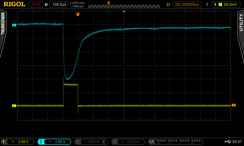
Lacking any of these another simple way is to check the decay product of Radon captured by the air filter from an air conditioner or an air purifier. These have a relatively short half life (in the order of tens of minutes) so make sure you run the AC for a couple of hours and then measure the filter immediately. If the filter is fine enough to it will emit radiations at a rate many time higher than background in your area. The chart below shows the count reaching almost ten times the background and then following the exponential curve typical of radioactive decay.
| Attachment | Size |
|---|---|
| Arduino Sketch | 1.84 KB |