A new version of this project is available here
 The 80 column output of the Commodore 128 is the same digital RGBI used by the original IBM CGA graphics adapter. Unfortunately nowadays is quite difficult to find a monitor with the suitable RGBI input. The CGA2RGB adapter will convert the TTL RGBI to analog RGB suitable to be connected directly to a 15KHz capable RGB monitor or to the popular Gonbes GBS-8200 VGA converter.
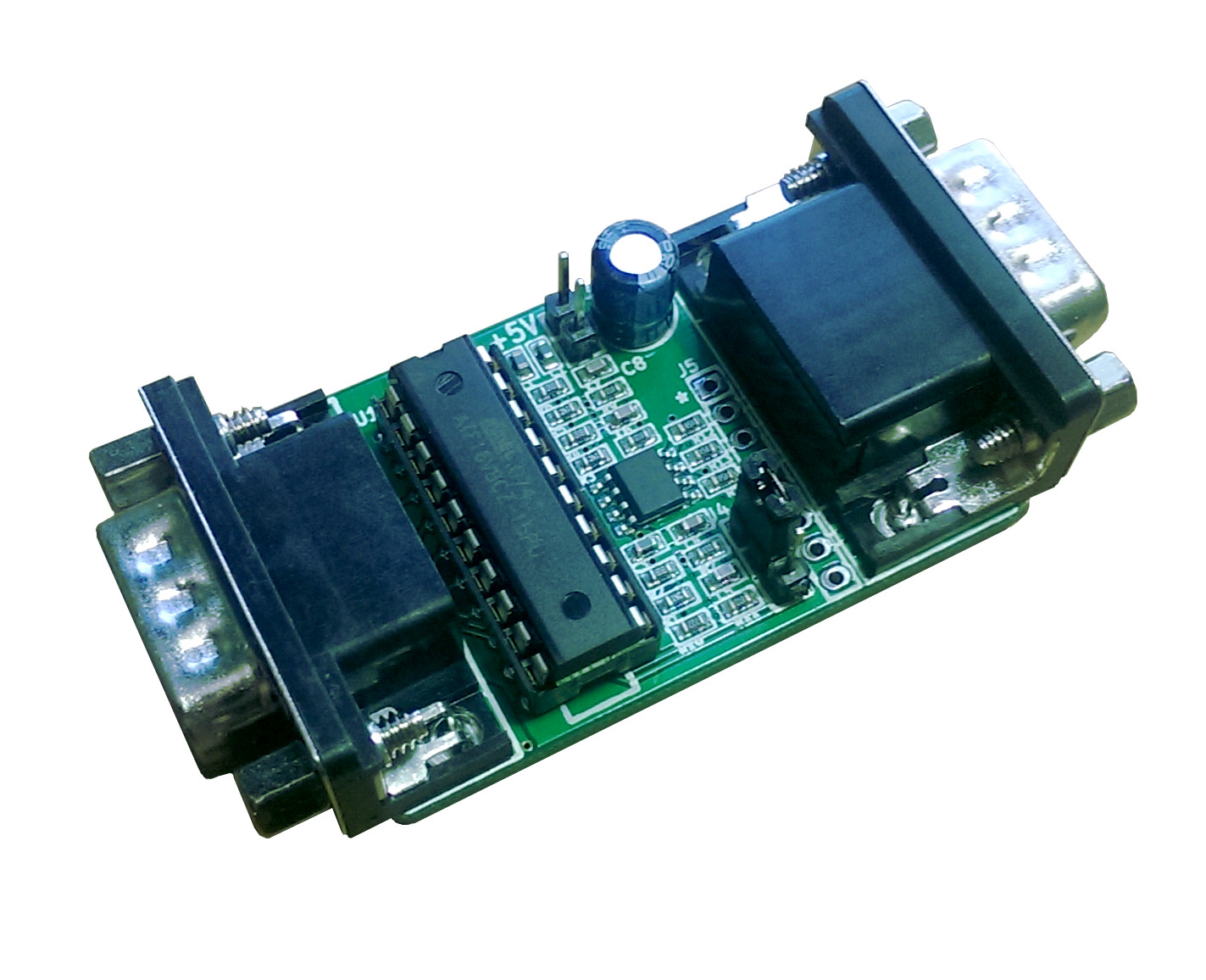
Similarly to the older CGA2RGB-B00, the basic circuit is a triple 2-bit digital to analog converter. The main improvement is the addition of J5 to improve the support for SCART and third party cases. Small capacitors have also been added to the output of the DAC to improve signal integrity.
U1 decodes the 4-bit RGBI input to the full 2-bit per color component and generates the composite sync needed for the GBS-8200.
The decoding follows the standard CGA color table which includes a special case for color 6.
| Commodore Color Number | CGA Color Number | RGBI | Color | R | G | B |
|---|---|---|---|---|---|---|
| 1 | 0 | 0000 | Black | 00 | 00 | 00 |
| 7 | 1 | 0010 | Blue | 00 | 00 | 10 |
| 6 | 2 | 0100 | Green | 00 | 10 | 00 |
| 12 | 3 | 0110 | Cyan | 00 | 10 | 10 |
| 3 | 4 | 1000 | Red | 10 | 00 | 00 |
| 9 | 5 | 1010 | Magenta | 10 | 00 | 10 |
| 10 | 6 | 1100 | Brown | 10 | 01 | 00 |
| 16 | 7 | 1110 | Light Grey | 10 | 10 | 10 |
| 13 | 8 | 0001 | Grey | 01 | 01 | 01 |
| 15 | 9 | 0011 | Light Blue | 01 | 01 | 11 |
| 14 | 10 | 0101 | Light Green | 01 | 11 | 01 |
| 4 | 11 | 0111 | Light Cyan | 01 | 11 | 11 |
| 11 | 12 | 1001 | Light Red | 11 | 01 | 01 |
| 5 | 13 | 1011 | Light Magenta | 11 | 01 | 11 |
| 8 | 14 | 1101 | Yellow | 11 | 11 | 01 |
| 2 | 15 | 1111 | White | 11 | 11 | 11 |
The resistor network R1,R2,R7 forms a simple R2R D/A converter. The output impedance of the converter is however too high to directly drive the 75ohm video cables. U2 buffers the signals and thanks to R12,R13,R15 provides a perfectly matched 75ohm impedance.
The board requires a 5V power supply. It can be powered directly from the GBS-8200 or using an external power supply.
Jumper J4 allow to select between composite sync (pin 1-2) suitable for the GBS-8200 and separate sync (pin 2-3) suitable for 15KHz capable monitors.
Connector J5 can be used for internal connections.
| Pin | Signal |
|---|---|
| 1 | GND |
| 2 | B |
| 3 | G |
| 4 | R |
| 5 | GND |
| 6 | VSYNC |
| 7 | HSYNC/CSYNC |
| 8 | Video |
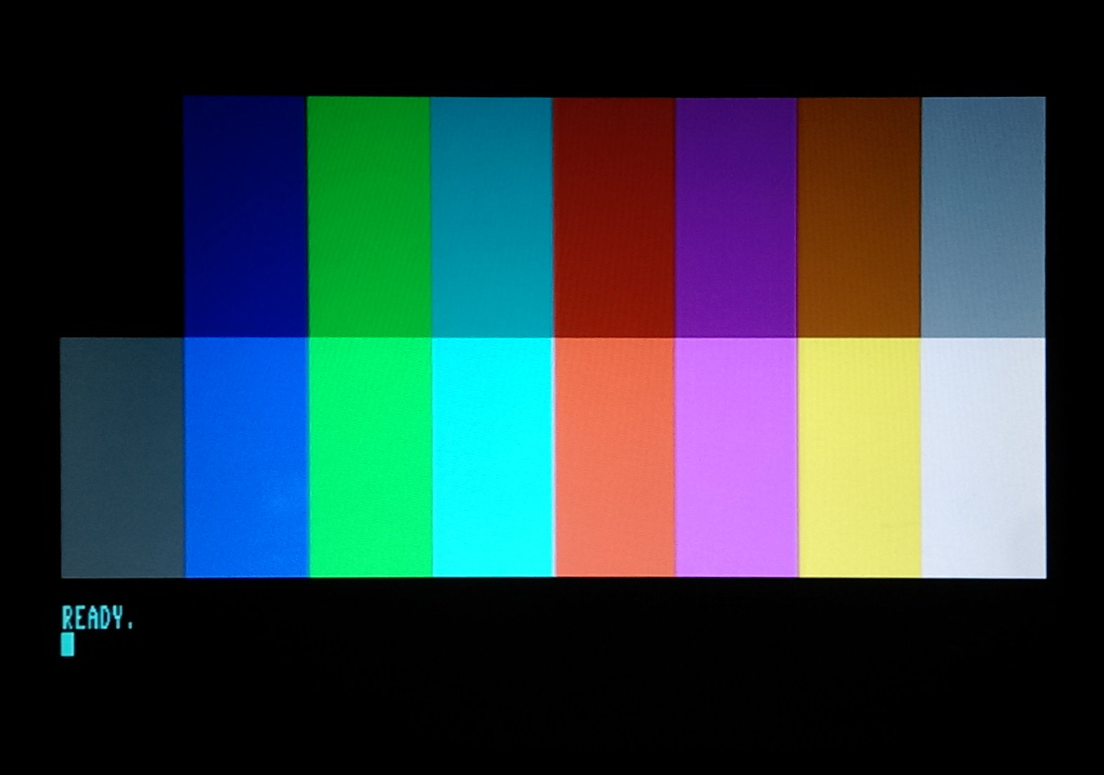
Image Quality
The image quality of the GCA2RGB, like all analog video connections, heavily depends on the cable used. The standard multi colored cable included in the GBS-8200 is not an optimal choice. The recommended configuration is to plug the CGA2RGB directly into the GBS HDB-15 input. If this is not an option a good quality VGA Male to Female cable should be used.
Great care has been devoted to produce a sharp and noise free signal. the following pictures show the waveform for a single pixel line and a 1 to 7 pixel. Rise and fall times are about 20ns with no visible overshoot.


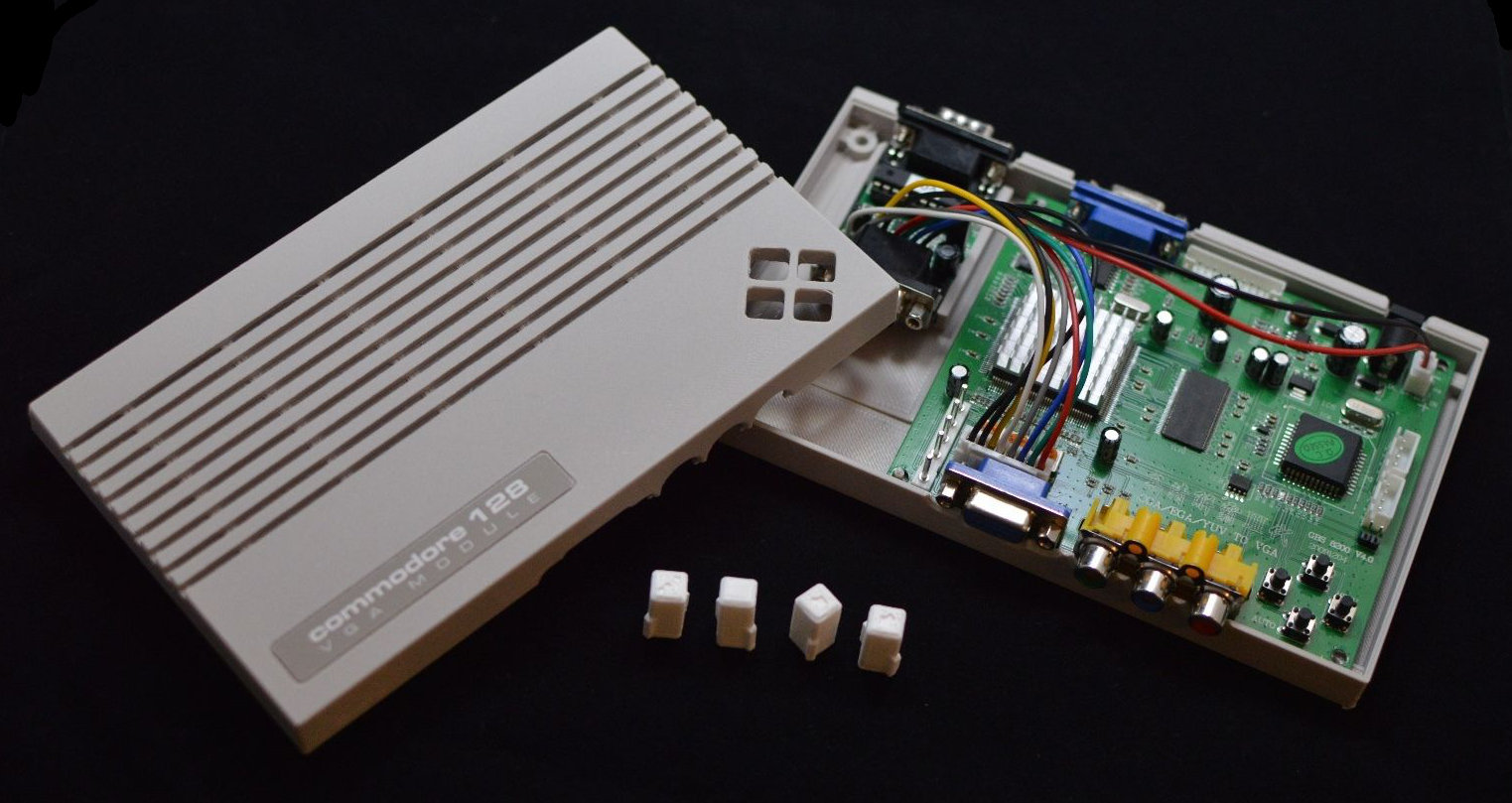
3D Printed CGA2RGB Cases
Our friends at Paez3D have developed a fantastic case for the CGA2RGB plus the Gonbes scaler. Please visit their website for information on how to purchase one.
IBM PC CGA to dull VGA generic flat screen display
Hi there,
I'd like one of these to attach to a IBM CGA 9pin video out to a generic VGA monitor.
Do you still have these and can you provide the cables as well?
kindest regards
Stephen Walters
London UK.
CGA2RGB availability
Hello,
CGA2RGB is available on eBay. The internal cables for connecting CGA2RGB to a scan doubler (like the GBS-8200) are *usually* provided with the scan doubler. Typically, you will receive a cable for video and another for power - both of these cables plug in to the GBS-8200 and the CGA2RGB (you will need to solder to the CGA2RGB if you use these cables). You will use both cables to drive the CGA2RGB. GBS-8200 scan doublers are available on eBay for a modest price. Be sure to confirm with your seller that the internal cables are provided, if you intend to use those cables to connect your CGA2RGB to the scan doubler.
For connecting the IBM's CGA port to the CGA2RGB: a 9-pin M-F cable (also available on eBay) is what you'll need. These can be serial cables but go with a shorter cable if possible.
As mentioned, enclosures are available as are complete solutions.
EGA?
Hi, will this work with EGA 640x350 (21.8 kHz) and the full 64-color palette?
EGA?
The CGA2RGB is specifically designed for CGA and will not work with EGA.
If there is enough demand we could consider a new design.
File for the GAL
Hi,
Where can I find the file for the GAL? I found the schematic, but the GAL would have to be programmed.
CSync Voltage Levels
If I set the jumper to choose CSync output, will I get sync levels I can use with Scart?
Csync Voltage Levels
the Csync voltage levels are optimized for a GBS style scaler and are not fully NTSC/PAL compliant.
Most TVs will be fine but Unfortunately not all of them.
If your CGA source has a b/w composite signal on CGA pin 7 (the C128 does) you can use that as a composite sync for the scart connector (the signal is also found on J5 pin 8.
Any for sale?
I would love to buy one of these to use with my Apple IIe RGB card. Any for sale?
New units will be available March/April 2019
We are working on a new improved design that supports EGA and MDA in addition of CGA.
Units should be available around March/April 2019
Progress?
I am very interested in this unit and have been waiting for its availability. It is now March 26, 2019, how is the development coming along? Are we still on schedule for a release soon?
I apologize for the delays in
I apologize for the delays in for the new version. There are very limited units for sale on ebay. Without proper SMT we can't build boards fast enough.
Update on new units?
Is there any update on new units to be released for this?
Thanks!
Connections
I'm a little confused. To get 80 columns in color from my 128, what exactly do I need? I get that I need the CGA2RGB and a Gonbes scaler (which one--8200 or 8220?), but if I get the case from Paez3D, then I also need 3 different cables, right? One VGA cable, one RGBI cable (same connector on both ends?), and what to connect this unit to the Gonbes? And 40 columns would require a separate composite to VGA converter, correct?
Connections
as a minimum setup you need a CGA2RGB, a scaler with VGA connector input (either the gonbes 8200 or the 8220 will work), a DB9 straight cable (for the CGA signal) and a VGA cable (from the scaler to the monitor).
If you purchase the Paez 3D case you will need to use the cable that usually comes with the gonbes to connect the CGA2RGB to the gonbes internal connector (soldering might be required in this case).
If you don't want to solder, I believe Paez 3D will also sell complete units with all the required components assembled and tested.
Build one on my own?
Hi, I see you provide the schematic for this... but I have a couple of questions...
First, since I am not familiar with the ATL16V8CZ, does this require programming
(from it's datasheet: it's a high performance EECMOS programmable logic device) or does it just plug in and go?
Second, I noticed on some of the other projects, there are included gerber files... is there one available for this?
Thank you!
Missing manufacturing files
We had problems in the past with dishonest individuals who copied our PCB/code and sold them without abiding to the GPL license (no proper credit given, no design files). This forced us to stop publishing all the files for anonymous download.
If you are still interested and are willing to respect the licensing terms, please send GG a message and we will send you the required files.
Using CGA2RGB with Scart cable
Hi there,
I've purchased an CGA2RGB-B01 adapter some time ago, and I would like to use this adapter
with a Scart cable towards the TV, in order to maintain compatibility with the 15kHz scan rate
without further external devices involved.
I've made an 15pin d-sub to Scart cable to carry the RGB and the composite sync signals towards
the TV. Pins 1 and 2 of J4 jumper are shorted in order to pass the composite sync through to pin 13
of the VGA connector. After powering up everything (including the CGA2RGB board with external 5V)
I got only a blank screen. Sync is seems to reach the TV, because as I turn off the computer the
"no signal" message appears on the screen shortly.
The cable was wired the following way:
SVGA pin / Scart pin / Desc.
1 -> 15 Red
2 -> 11 Green
3 -> 7 Blue
6 -> 13 Red GND
7 -> 9 Green GND
8 -> 5 Blue GND
10 -> 18 Sync GND
13 -> 20 Sync
Is this OK, or maybe I'm missed something?
SCART cables
The csync output from the CGA2RGB is optimized for the GBS scan converters and it is not totally compliant to the TV specifications.
What is the source of the CGA signal? If your source outputs B/W video on CGA pin 7 you can use that for the SCART CSYNC (this signal is available on J5 pin 8)
Feedback in regard of using CGA2RGB with Scart cable
Hello,
The source of the CGA signal is an RGBI output of a Commodore 128.
In the meantime I've managed to find the problem: it is necessary to provide
the "RGB select" signal for the TV. Pin#16 of the SCART connector must be pulled up 3 to 5 Volts
in order to switch into RGB mode. Below 3V the SCART input operates as composite,
and the display goes blank.
Providing this RGB signaling, my TV/monitor displays the picture correctly,
without any extra devices. So the cable was basically OK, only this signaling
was needed in order to work.
question
Hi, i'm just curious, the only way to get this is purchasing it? i am guessing i can't build it myself without the 16v8 code.
GAL code
See the reasons in a comment above on why we don't include the GAL files in the page.
If you are still interested and are willing to respect the licensing terms, please send GG a message and we will send you the required files.
Availability
Hi, I saw a reply earlier where you mentioned March/April for supply of new units. Do you have an update on when they will be available to buy?
Thanks!
Mike
Hopefully the wait will not be long
The design is going to the final validation stages and it is almost ready for batch production.
Compatibility
will this would for tandy video (TGA, Tandy 1000, extended CGA Digital RGBI)
Tandy 1000
The CGA2RGB works well on the Tandy 1000
I've purchased this adaptor a year ago for PC XT
Hello, I have an XT PC with the DB9 video connector, and also an old monitor that show the image poorly because of the bad state.
I wish to replace it with this adaptor, regardless the 5V power source what I need to use a standard VGA CRT monitor.?
This adaptor does all the job or I do need another board, like the one showed in the 3d printed case?
Best regards in advance.