A new version of this project is available here
 The 80 column output of the Commodore 128 is the same digital RGBI used by the original IBM CGA graphics adapter. Unfortunately nowadays is quite difficult to find a monitor with the suitable RGBI input. The CGA2RGBv2 adapter will convert the TTL RGBI to analog RGB suitable to be connected directly to a 15KHz capable RGB monitor or to the popular Gonbes GBS-8200 VGA converter. As an added bonus the CGA2RGBv2 can also convert MDA and EGA to an analog format for the enjoyment of all our retro PC friends.
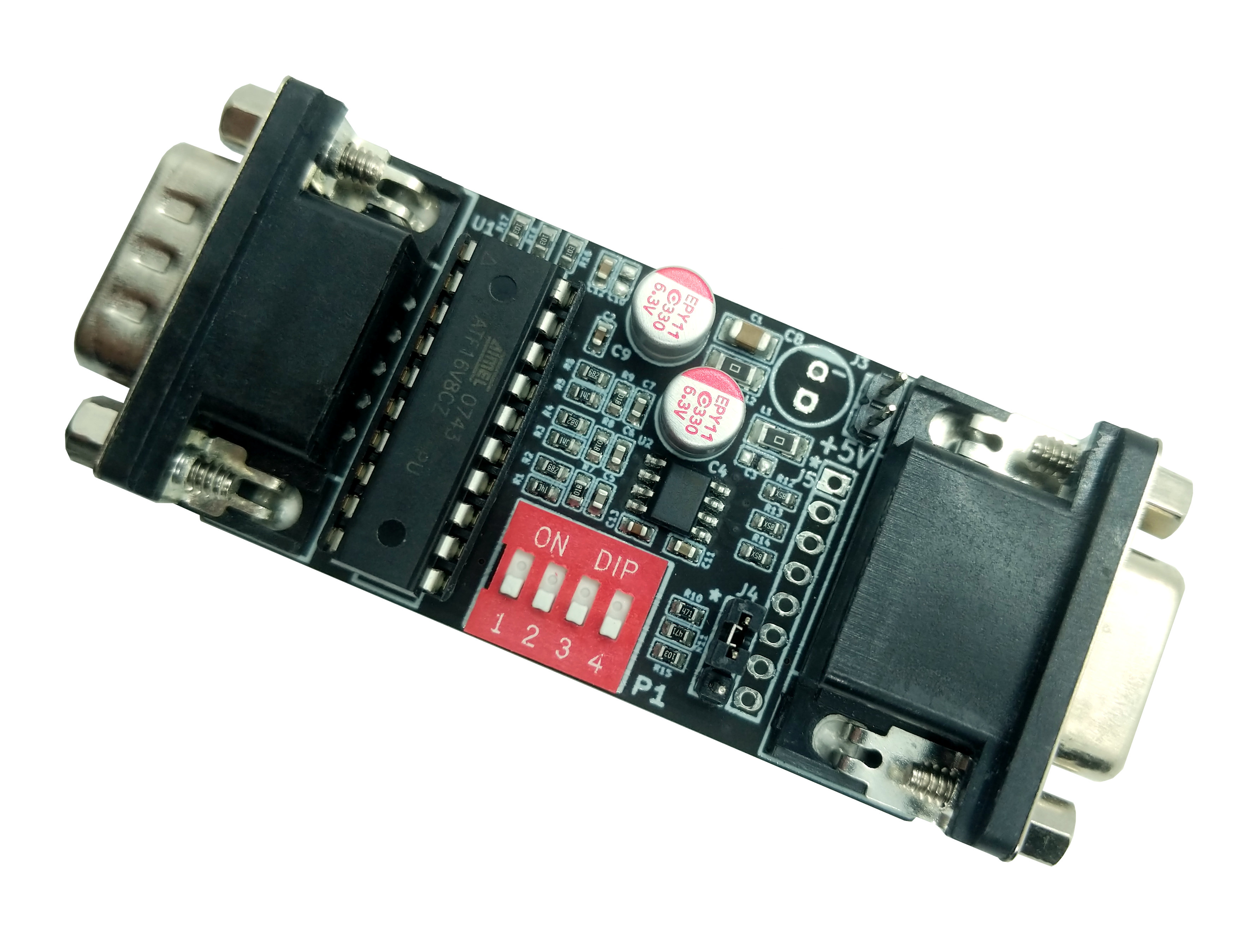
Similarly to the older CGA2RGB-B01, the basic circuit is a triple 2-bit digital to analog converter. The main improvement is the addition of a dip switch to select the mode of operation and the improved power filtering to improve image quality with cheap power supplies.
U1 decodes the RGBI input to 2-bit per color component according to the dip switch settings and generates the composite sync needed for the GBS-8200.
| Mode | DIP1 | DIP2 | DIP3 | DIP4 |
|---|---|---|---|---|
| CGA | OFF | OFF | OFF | OFF |
| EGA | ON | OFF | ON | ON |
| MDA White | ON | ON | OFF | OFF |
| MDA Green | ON | ON | ON | OFF |
For MDA the converter supports enhanced brightness and can be configured for white or green for a more retro look.
For EGA the conversion is direct as the digital signal is already 2-bit per component.
For CGA the decoding follows the standard color table which includes a special case for color 6.
| Commodore Color Number | CGA Color Number | RGBI | Color | R | G | B |
|---|---|---|---|---|---|---|
| 1 | 0 | 0000 | Black | 00 | 00 | 00 |
| 7 | 1 | 0010 | Blue | 00 | 00 | 10 |
| 6 | 2 | 0100 | Green | 00 | 10 | 00 |
| 12 | 3 | 0110 | Cyan | 00 | 10 | 10 |
| 3 | 4 | 1000 | Red | 10 | 00 | 00 |
| 9 | 5 | 1010 | Magenta | 10 | 00 | 10 |
| 10 | 6 | 1100 | Brown | 10 | 01 | 00 |
| 16 | 7 | 1110 | Light Grey | 10 | 10 | 10 |
| 13 | 8 | 0001 | Grey | 01 | 01 | 01 |
| 15 | 9 | 0011 | Light Blue | 01 | 01 | 11 |
| 14 | 10 | 0101 | Light Green | 01 | 11 | 01 |
| 4 | 11 | 0111 | Light Cyan | 01 | 11 | 11 |
| 11 | 12 | 1001 | Light Red | 11 | 01 | 01 |
| 5 | 13 | 1011 | Light Magenta | 11 | 01 | 11 |
| 8 | 14 | 1101 | Yellow | 11 | 11 | 01 |
| 2 | 15 | 1111 | White | 11 | 11 | 11 |
The resistor network R1,R2,R7 forms a simple R2R D/A converter. The output impedance of the converter is however too high to directly drive the 75ohm video cables. U2 buffers the signals and thanks to R12,R13,R15 provides a perfectly matched 75ohm impedance.
L1 an L2 and the related capacitors provide noise filtering some isolation between the analog and digital portion of the board.
The board requires a 5V power supply. It can be powered directly from the GBS-8200 or using an external power supply.
Jumper J4 allow to select between composite sync (pin 1-2) suitable for the GBS-8200 and separate sync (pin 2-3) suitable for 15KHz capable monitors.
Connector J5 can be used for internal connections.
| Pin | Signal |
|---|---|
| 1 | GND |
| 2 | B |
| 3 | G |
| 4 | R |
| 5 | GND |
| 6 | VSYNC |
| 7 | HSYNC/CSYNC |
| 8 | Video (if present, can be used as a CSYNC for SCART connections) |
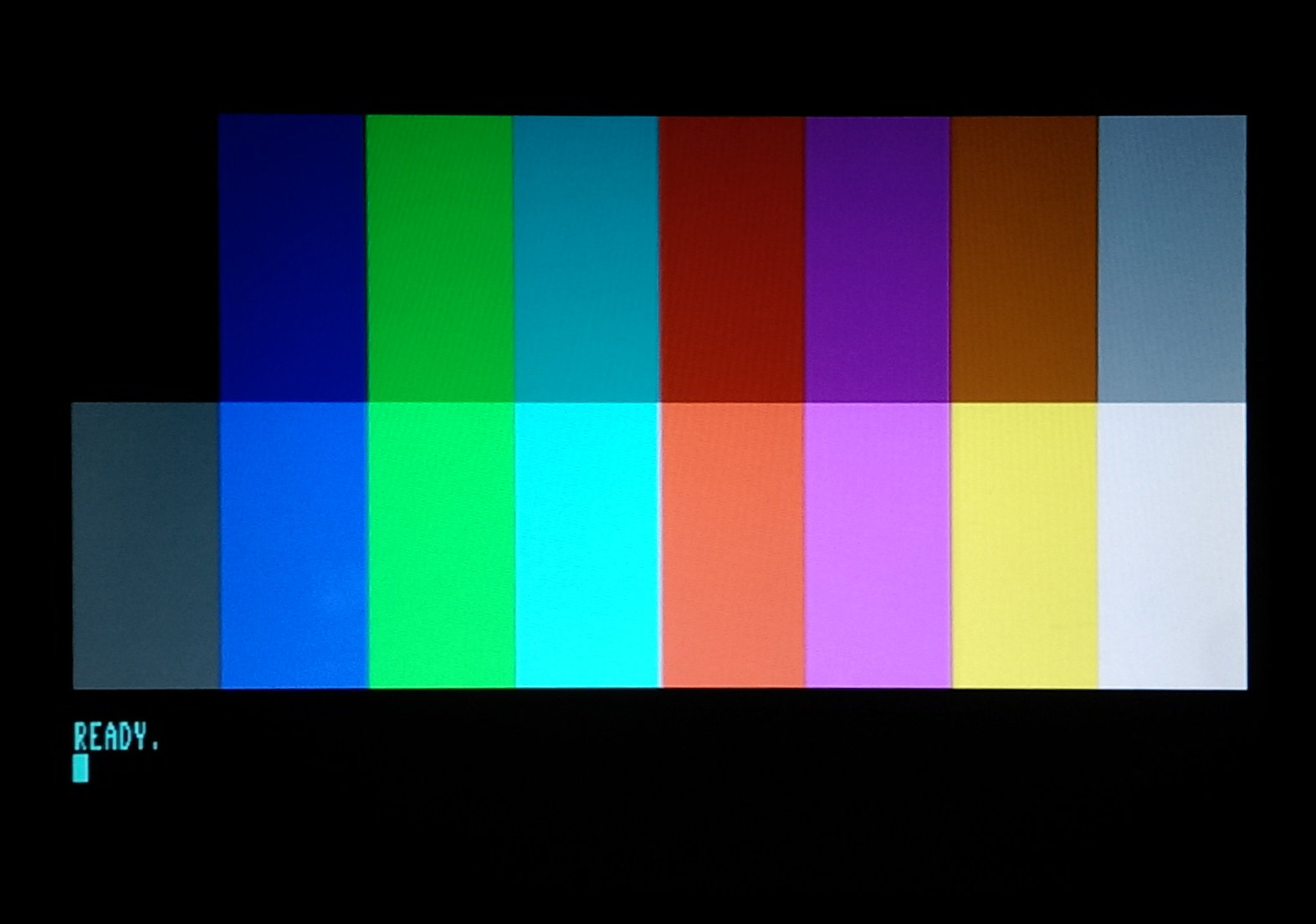
Image Quality
The image quality of the GCA2RGB, like all analog video connections, heavily depends on the cable used. The standard multi colored cable included in the GBS-8200 is not an optimal choice. For sharp images a good quality VGA cable should be used.
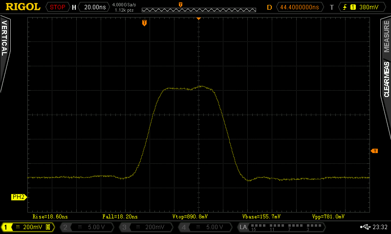
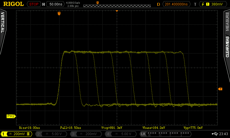
Great care has been devoted to produce a sharp and noise free signal. The following pictures show the waveform for a single pixel line and a 1 to 7 pixel. Rise and fall times are consistently below 20ns with very limited overshoot.
Power filtering has been significantly improved as well to produce a noise free image even when using cheap 5V power supplies.
Errata
The R and B label on the J5 silkscreen are swapped.
Scart sync stability
in a comment on the previous version, you said https://gglabs.us/comment/6380#comment-6380
> the Csync voltage levels are optimized for a GBS style scaler and are not fully NTSC/PAL compliant.
Did you make them fully compliant for this version?
The syncs are generated by the source computer
The composite sync is generated by simply combining the H and V sync provided by the computer. These are often not fully compliant with either NTSC or PAL standards (i.e. many machines do not output the correct number of serrated sync pulses in the front porch, output non standard 240p instead of 480i, etc...).
They are usually good enough for analog TVs but some modern TVs with digital decoders will fail to properly detect the signal.
For machines like the Commodore 128 that output a mono signal on pin 7 the best solution is to route the mono video to the composite sync pin (remove the jumper of J4 and connect J5 pin 8 to J4 pin 2)
How do I deliver power to the CGA2RGB?
I just purchased a CGA2RGB device last week (Dept 2019) and I have a Gonbes 8200. The Gonbes is having power delivered from a 5v adapter, but I can't find how to get power to the CGA2RGB. It has two pins that seem to be for power input, but I don't know what the name of the connector I need is. I found a barrel jack to 2-pin JST adapter on Amazon so that I can just plug it in with another 5v adapter, but the JST connector is way too small for the pins. Can anyone point me to the exact Barrel jack to 2-pin (whatever) connector or how I can get power to this device?
Powering the CGA2RGB
If you power the gonbes with 5V using the barrel jack you can use the power from the JST to power the CGA2RGB (the connector on the CGA2RGB is a standard 2-pin 2.54mm header).
Alternatively you can use any old 5V USB phone charger. Cut the cable and connect directly to the CGA2RGB.
Compatibility
is this compatible with the Tandy 1000 -TGA graphics- (TGA, extendted CGA)
Tandy 1000
Yes, the Tandy 1000 TGA outputs RGBI and is fully supported in CGA mode (all DIP switches off)
thank you
I got the unit but setting all switches to low and i get a rolling image but if i set 4 to on i get a desent image only the top is distored and jittery (Yes im aware it could be a issue with the gbs8200. but i wanted to know what the switch 4 sets and is it safe to run that way long term.
DIP Switch 4
Dip switch 4 selects between NOR composite sync (incorrect but seems the most compatible with GBS units) and XOR (correct logic operation but poor compatibility with GBS units).
The default OFF position selects NOR.
Order?
How do i order one?
Purchasing GGLABS Products
please refer to the page at https://gglabs.us/node/451